[Click Here to download our whitepaper "Using Membranes for Gas Exchange." (PDF)]
Silicone, composed primarily of polydimethylsiloxane (PDMS) and other siloxanes, is among the most gas permeable dense polymeric membrane materials available. Gases permeate silicone by a solution / diffusion mechanism, whereby the rate of gas permeation is directly proportional to the product of solubility of the gas, and the rate of diffusion of the dissolved gas in silicone. The permeability coefficient is a parameter defined as the transport flux of a gas (rate of gas permeation per unit area), per unit transmembrane driving force, per unit membrane thickness. The permeability coefficient for various gases and vapors in PDMS is presented in the table below. Silicone rubbers (such as in our membrane modules) is primarily PDMS and other siloxanes including silicone resins, so the gas permeability is a bit lower.
WARNING: A listing for the permeability coefficient for a specific gas is not an indication that the membrane is compatible with that gas. Membrane degradation and failure may occur with some gases and liquids. It is the responsibility of the user to determine the suitability of PermSelect® membrane modules in its specific application. Please view the silicone chemical compatibility chart and the polyurethane (potting) chemical compatibility chart as an initial substance compatibility guide.
| GAS NAME | FORMULA | PERMEABILITY COEFFICIENT (Barrer)* |
| Nitrogen | N2 | 280 |
| Carbon monoxide | CO | 340 |
| Oxygen | O2 | 600 |
| Nitric oxide | NO | 600 |
| Argon | Ar | 600 |
| Hydrogen | H2 | 650 |
| Helium | He | 350 |
| Methane | CH4 | 950 |
| Ethylene | C2H4 | 1350 |
| Ethane | C2H6 | 2500 |
| Carbon dioxide | CO2 | 3250 |
| Propane | C3H8 | 4100 |
| Nitrous oxide | N2O | 4350 |
| Acetone | C3H6O | 5860 |
| Ammonia | NH3 | 5900 |
| Nitrogen dioxide | NO2 | 7500 |
| Octane | n-C8H18 | 8600 |
| Butane | n-C4H10 | 9000 |
| Toluene | C7H8 | 9130 |
| Hexane | n-C6H14 | 9400 |
| Hydrogen sulfide | H2S | 10000 |
| Benzene | C6H6 | 10800 |
| Methanol | CH3OH | 13900 |
| Sulfur dioxide | SO2 | 15000 |
| Pentane | n-C5H12 | 20000 |
| Water | H2O | 36000 |
| Carbon disulfide | CS2 | 90000 |
*1 Barrer = 10-10 cm3 (STP)· cm /cm2 · s · cm-Hg Unless otherwise noted, permeabilities are measured and reported at 25C (RTP) and not (STP) From: THIN SILICONE MEMBRANES-THEIR PERMEATION PROPERTIES AND SOME APPLICATIONS Annals of the New York Academy of Sciences, vol. 146, issue 1 Materials in , pp. 119-137 W. L. Robb | ||
Therefore the rate of gas transfer across the membrane is proportional to the gas permeability coefficient, the membrane surface area, the trans-membrane gas partial pressure difference, and inversely proportional to the membrane thickness. Thus gas transfer across a membrane increases with increased gas permeability coefficient, increased surface area, increased transmembrane gas partial pressure and decreased membrane thickness.
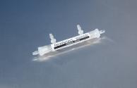
PermSelect ® silicone membranes are configured into hollow fibers which are small silicone micro-tubes with very thin walls which act as membranes. If there is a gas specie partial pressure difference between the inside and the outside of the hollow fiber membrane, that gas specie can permeate across the thin silicone walls in the direction from high to low gas partial pressure. Thus configuring membranes into hollow fibers enables the packaging large amounts of membrane surface area in very compact volumes. Moreover, hollow fibers constitute a self supported, inherently stable membrane structure that can tolerate high pressure differences between the inside and outside of the hollow fiber membrane.
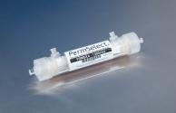
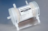
Hollow fiber membranes are typically packaged in membrane gas exchangers or membrane modules in which thousands of hollow fibers are bundled in a very compact volume and sealed or potted within a housing as shown in the figure below. Consequently, the sum of the surface area of each individual hollow fiber membrane constitutes the total membrane area for the gas exchanger (or module), and it becomes apparent how it is possible to achieve high membrane surface densities with hollow fiber membranes.
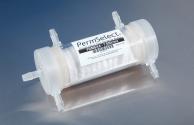
Membrane modules and gas exchangers will typically have an inlet and an outlet port in fluid communication with the inside of all the hollow fibers (also known as tube side) which are manifolded at both ends of the fiber bundle. Similarly the membrane gas exchanger module will have one or more ports in fluid communication to the outside of the hollow fibers or the shell side.

PermSelect® silicone membrane gas exchanger and modules can be used for liquid contacting and gas separation applications. The side of the hollow fiber membranes (shell or tube) in which a gas or liquid should flow will depend on the specific application for the membrane gas exchanger, and is selected to maximize membrane module performance. For example, as shown in the figure below, in membrane gas separation a feed mixture of gases enters the membrane module through the inlet port to the tube side and flows through the inside of the hollow fiber membranes. The gas species in the mixture with higher permeability will transfer at a greater rate across the walls of hollow fiber membranes leaving behind the less permeable species. The transferred gas is referred to as the permeate. In the shell side, a vacuum can be applied or a sweep gas (or liquid) can flow therein to carry away the permeate. Exiting the outlet of the tube side is the retentate which constitutes a gas mixture with a higher concentration of the less permeable gas species.
Membrane Gas Separation. Although the permeability ratio for two gases in a binary gas mixture provides a gross estimate for the ratio of permeate flow for the two gases, actual measurements show that the interaction of a gas mixture on the membrane can affect permeation rates. Moreover feed and permeate pressures can also affect permeation rates as the membrane structure can change under pressure. The membrane gas separation factor is a membrane property that is useful in determining permeation rates for mixtures of gases under certain operating conditions. We have measured the membrane gas separation factors for a series of feed gas mixtures using PermSelect® silicone membranes. Click here to see a table of separation factors.

Liquid Contacting. Adding and removing dissolved gases from liquids can be easily accomplished using PermSelect® silicone membrane gas exchangers and modules. A liquid stream flows on one side of the membrane and a mixture of gases flows on (or vacuum is applied to) the other side of the membrane. Each gas specie flows from the side of the membrane with higher partial pressure to the side with lower partial pressure, thereby tending to equilibrate both sides. Thus it is possible to control the dissolved gases in a liquid stream flowing through the module by controlling the gas mixture (or vacuum) applied.
Please view the video below explaining how our membrane gas exchangers can be used to control dissolved gases in liquids.
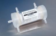
PermSelect® silicone membranes gas exchanger and modules can handle high temperatures, UV, and oxidizing environments. Also, because the membrane is dense, there are no pores that can foul or wet-out, enabling use of the modules with low surface tension liquids. Our membrane modules provide a highly efficient radial flow design through a densely packed bundle of uniformly spaced apart hollow fibers. Our membrane modules are available commercially with membrane surface areas of ten, 100, 1,000, 2,500, 7,500 centimeters square; and 1.0 and 2.1 meters square. contact us to discuss your specific requirements.
Our versatile membrane gas exchangers have been used to control gas levels in liquids including for degassing liquids in pharmaceutical industry, media gas control in cell culture bioreactors, degassing inks, and degassing water. Our membranes are also ideal for humidifying gas streams (such as for fuel cells); to separate VOCs and solvents from water and air, and to remove moisture from gas streams.
Please view below a series of short videos demonstrating how simple it is to use PermSelect® silicone membrane gas exchangers and modules for your gas exchange needs.
| Liquid Degassing Silicone membrane contactors and degassers can be used effectively for continuously degassing liquids, including low surface tension liquids and many compatible solvents. Since the membrane is dense, there are no pores to wet-out and foul. View a video demonstrating how to use a PermSelect® membrane module to degas a liquid stream. | |
| Gas Dehumidification Gas stream dehumidification using PermSelect® membrane modules can be accomplished very quickly and easily. Because silicone membranes are highly permeable to water vapor they are very efficient in transferring moisture out of gas streams while preserving other gases substantially intact. View a short video demonstrating how to use a PermSelect® membrane module to dehumidify your gas stream. | |
| Liquid Gas Control (Gassing) Liquid gas control can be effectively accomplished using PermSelect® membrane modules and contactors. Dissolved gases in liquids can be easily equilibrated with target gas mixtures simply by flowing the liquid and gas on opposite sides of the silicone membrane. View a short video demonstrating how to use a PermSelect® membrane module to add gases to your liquid stream. | |
| Gas Humidification Gas humidification can be effectively accomplished using PermSelect® membrane modules. Due to the high permeability of water vapor in silicone, substantial amounts of water vapor can be passively added to your gas stream without need for boiling water or bubbling your gas through water. View a short video demonstrating how to use a PermSelect® membrane module to humidify your gas stream. |